


Did you make the adapters yourself?Originally Posted by bobfish4blac


|
|
|
|
|
|
 Registered User
Did you make the adapters yourself?
Dream Platform
Registered User
yes i did, but i don't have a online url to show them from, but u can see them on reef central, dream chip thread
Registered User
I'm interested in what everyone is doing about the exposed copper parts of the chip cooler? Isn't anyone worried about the saltwater condensation on the copper? I would think at night when the lights are not on, the copper will be very cool and condensation will form. Is this anything to worry about?
Registered User
Now after nearly 9 months since this amazing race (with the Dream Chip) started I have my Dream Chip running over my aquarium and Im very pleased. My configuration (or dream) included a small and dedicated driver card so I could build everything into one container and only have a power cord and a communication cable into the lamp. There was a lot of Swedes in the first group buy and even in the second run there rise a demand of a dedicated driver card for the Dream Chip. One of the Swedish guys decided to develop such a driver card and to develop a configuration program for Windows. The demands on the driver card was that power source should be plus - minus 36V, small footprint, communication between 5 different driver cards and to a controlling unit with 4 separate inbuilt dimmer functions (ramps with at least 6 breakpoints), delay function, temperature control and management of fans for both the driver card and the LED-chip, automatic shout down for high temperatures, individually current adjustment to each channel and much more. I started my finally build in late November and also served as a beta tester for Janne´s driver card.
My first idea was to use these graphic card coolers
I used this coolers when I started to test the driver and controlling cards: here is a beta version of the driver card.
Now I think did one of my mistakes when I attached the lens to the LED chip with two components epoxy. I later on take away the lenses and finally attached them with heath proof silicon from AC-RC. Why - misstake? Later on when I tested the LED chip I burned out two and both of them was in the beginning attached with epoxy. Three other LED chips - lenses only attached with heat proof silicon - still working without any dammages.
Here I run the LED chip with 140 mA - roughly 20 W
After a lot of testing and thinking how I should do the best solution both in a practical and an esthetically way - I decided to skip the graphic coolers and instead use a processor cooler - Zalman CNPS8900 Extreme
As RColeman I am worried about to expose to much of copper over the aquarium and I did not plan to use any enclosing below the LED chip because I want the air blowing down to the surface of the water just to rise the evaporation rate (more evaporation - cooler aquarium. It is true the air blowing down from the cooler is warm - but it is therefore more dry - and that means a lot according to evaporation). I decided to paint them with a heat proof black colour.
Will be continued
Sincerely Lasse
Registered User
As a container I chose a PVC tube with a diameter of 140 mm
I attach the driver card to the container and make the container black.
Mount attaching points for the cooler
Mount the cooler and LED chip to the container
When I mounted the LED chip to the cooler I use a high quality thermal compound as Artic Cooling MX-2. With this cooler you can attach the LED chip directly to the cooler plate using two bolts. I had to make two of the attaching holes at the LED chip a little bit larger. I mount the chip at two attaching holes in the cooler (diagonally).
The containers was mounted to aluminumum U - channel
The last test
Because I burned out two chip´s I had to use a 50 LED chip in the middle:
and for the right cannon I had to use a chip that I had ordered for other purposes (freshwater)
I am going to test the red channel here but I´m only running it at 500 mA and at 15 % intensity.
Here is the first test run over the aquarium. Around 50 % blue and 20 % white
Here I running 100 % of around 100 W of each cannon
I´m comming back
Sincerely Lasse
Last edited by Lasse; 03-09-2013 at 08:20 AM.
Registered User
build me one....lol
Registered User
How are the driver cards working for you? Are there any available ?
Registered User
I´m very pleased with the driver card and the control card. Janne was a little bit worried because I succeeded to damage two chips the same way you did but we have turn in and out and we do not think that it is something wrong with his driver card I have run this three "cannons" for 6 day now without any damages on the chips and I tested for a week before I hang them over my aquarium. I think that there is a bunch of cards going out to other swedes this week . Contact Janne and ask him. I know that there is no manual ready yet. How are things going with your setup?
Sincerely Lasse
Last edited by Lasse; 03-12-2013 at 01:26 PM.
Registered User
Well I've had chips over my tank for 4 months now, although there seems to be a problem with uv channels, I have whites of 2 chips on one driver .Blue and uv on another driver. Chips are mounted about 30cm above water with no lenses, water depth 70cm and I'm getting good growth on sps and lps.
Registered User
I would like to thank Ron, Bob, Lasse, and Janne for all the help they gave me designing my DreamChip setup. Although the symbols are not correct, I think you will get the idea of my setup. I wanted a way to disconnect the lights from inside the canopy and connect to the drivers and fuses outside the canopy. I was really puzzled at how I would accomplish this until I drew it out. Maybe this can help someone else like me that has no electronics experience or knowledge. Use this design at your own risk, as I have not assembled it yet, I'm waiting on my fuse block and XT60 connectors.
If anyone see anything wrong with this setup, please let me know. Thanks
**** I have assembled as drawn, and it works! **** Ramp function tested as well.
[IMG][/IMG]
Last edited by RColeman; 04-12-2013 at 11:47 AM.
Registered User
Hi Lasse, Nice to hear from you, and really like your fixtures. Question, how do the DC's 10 wires attach to the drive card?---Rick
Registered User
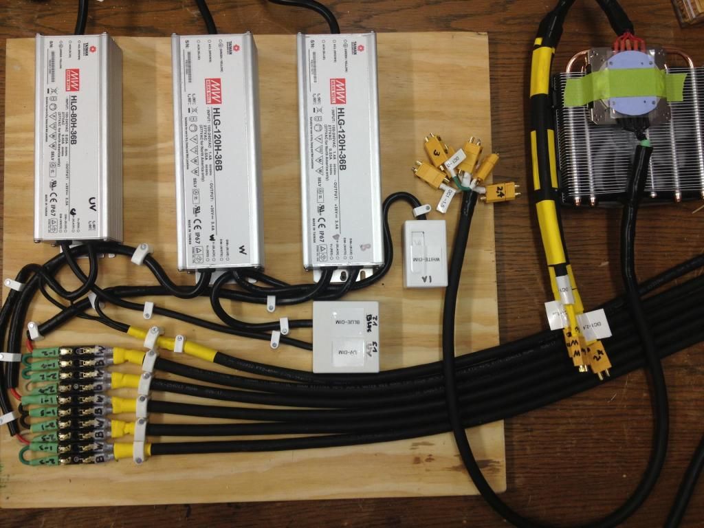
The card is constructed with a common +. Look at this picture
To the right. The first blue is minus from the DC power, the brown is plus from the DC power. The third cable (red) is all 5 plus from the chip. cable 4 (yellow) is minus from channel 1, cable 5 (brown) = minus from channel 2 and so on.
Sincerely Lasse
Registered User
Interesting Lasse,...Janne's card lets you tie all five pluses together.
I'm still planning on the 8900 and 5" PVC, but I'm going to use Meanwell LDD1000's on this card
You can see on the card I need 2 wires for power, 5 PWM wires back to my controller, and then each red and black wire from the DC to the 5 LDD's + - the card is approx. 4"x4" ---Rick
Registered User
From each of my three cannons I have 1 DC cord (minus and plus) Between the cannons there is a CAT 5 network cable and one CAT 5 cable out to the controller. I run two driver card from the same power source, the third cannon has its own power source. The temperature controller of the LED chip and the power to the coolers fan comes from the driver card. it is very simple and clean.
I have read a little about the meanwell solution and I think it is a great solution also
Sincerely Lasse
Registered User
Our builds are very similar. I'm going to locate my drivers at the cannons also, and don't know if you recall, I'm planning on 4 DC's. I'll have 1 PS @ 2 DC's. I'm also going to tie my 5 channels on each DC together and then back to my controller with cat 5's my fans power, pwm and the DS18B20 will be on another cat5. So I'll have 1 power and 2 cat5's to each cannon. I'm building a Jarduino controller to run it all.
There are currently 1 users browsing this thread. (0 members and 1 guests)
 Posting Permissions
 Reply With Quote